- Loading Eagle and starting a new project
- My first ever shematic
- image 3- Importing and using a Componetnt Library
https://learn.adafruit.com/eagle-tutorial-how-to-add-a-new-package-to-a-component/new-library
- I would advise to add all the components that you will need into the schematic, it just make life much easier seeing things in a bigger picture.
- I would strongly advise assigning the different values to the components you plan to use. On the left hand side of the schematic tool bar, you will find two functions, one for the name of the component and another for the value of the component. I would also strongly recommend adding ground component (GND) that you can find in when adding components from the libraries.
- To connect each component with lines you use the net function on the tool bar. Make sure all your components are probably connected before carrying on. You can also name the components and a window will pop up to link them.
- In the tool bar you will also find move and copy items to re-organize the components to make a easy to understand schematic.
- Once your schematic is ready you can select the Generate/Switch to board function on the top toolbar. This will pop up a new window with all your components.
- This window has a grid layout which I would highly recommend as it will make positioning and organizing for you components much easier.
- Whilst organising your board there is a Rats Nest function on the side bar which will calculate simple routs for you paths to run, it was advised to do this with the tutorial but with designing the Hallo world you most likely will not use it.
- Once all the components are pleased and Rats nest has been performed then you can set the Auto Route function (which you will align probably not use for designing your hallo world).
-
This tutorial shows you how to make a double sided circuit board, but for the hallo world you will only make a single sided board. With this board the positive charges (Red) are on top and the negative on the bottom (Blue). To connect the two layers in different areas you use VIA which is a hole with conductive material to link the top and the bottom.
 Changing Top to positive and the bottom with ground.
-
- Setting up route files
- Done
-
NOW FOR MY Hallo World
- Download the Library for Hallo World (Fab Library)
- Then get a schematic and board layout from a Student from the past years and print it out on paper (This really helps).
- Add all the components that you will need for your Hallo World
- Assign Names and Values to the components and place them in an orderly fashion.
- Start linking them with either the Name tool or with the Net Tool.
- Switch to Board layout and drag all the components into the routing area and set your grid for manual routing (Manual routing makes everything much easier then auto routing).
- Grid Spacing
(DO THIS, I WILL NOT SAY THIS AGAIN...)
- Whilst manual routing (Route - Blue squiggly line on the side toolbar)it is important to remember that 1)your lines do not touch (give enough clearance between) 2) keep your head (you will be doing this a few times to get it perfect)
- Then use the Polygon function to draw how you want the board to look like and check you design (DRC Function).
- Now Done with my Hallo World and now to export it to png and rout it out.
-
COMMING SOON... REAL SOON...PLEASE COME BACK SOON...
- Resistors- Wat do they actually do?
A resistor is a passive two-terminal electrical component that implements electrical resistance as a circuit element. Resistors act to reduce current flow, and, at the same time, act to lower voltage levels within circuits.
For Definition and a lot more https://en.wikipedia.org/wiki/Resistor
-
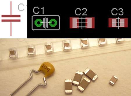
- Capacitor- Wat do they actually do?
Materials commonly used as dielectrics include glass, ceramic, plastic film, air, vacuum, paper, mica, and oxide layers. Capacitors are widely used as parts of electrical circuits in many common electrical devices. Unlike a resistor, an ideal capacitor does not dissipate energy.
For Definition and a lot more https://en.wikipedia.org/wiki/Capacitor
-
- Crystal 20Mhz or 20Mhz Rezonator- Wat do they actually do?
A crystal oscillator is an electronic oscillator circuit that uses the mechanical resonance of a vibrating crystal of piezoelectric material to create an electrical signal with a precise frequency. This frequency is commonly used to keep track of time, as in quartz wristwatches, to provide a stable clock signal for digital integrated circuits, and to stabilize frequencies for radio transmitters and receivers. The most common type of piezoelectric resonator used is the quartz crystal, so oscillator circuits incorporating them became known as crystal oscillators but other piezoelectric materials including polycrystalline ceramics are used in similar circuits.
For Definition and a lot more https://en.wikipedia.org/wiki/Crystal_oscillator
-
.jpg)
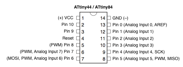
- ATtiny 44 Microcontroller- Wat do they actually do?
A microcontroller is a small computer (SoC) on a single integrated circuit containing a processor core, memory, and programmable input/output peripherals. Program memory in the form of Ferroelectric RAM, NOR flash or OTP ROM is also often included on chip, as well as a typically small amount of RAM.
For Definition and a lot more https://en.wikipedia.org/wiki/Microcontroller
Sum usefull links for microcontrollers and the DATA SHEET (Interesting and boaring read at the same time) http://www.atmel.com/devices/ATTINY44.aspx
A usefull link for programming the ATtiny 44 http://highlowtech.org/?p=1695
-
- Milling my hallo world
- cut out the board
-
after soldering all the components I plugged it in and hopefully now it’s ready for Programming in embedded programming.
Manufacturing my Hallo World
Learning Electronic Components
and finally here it is